Discover how to convert line-to-line voltage to line-to-neutral in 1 step with examples.
Use our conversion tables and formulas to correctly size transformers and protect three-phase systems.
Line-to-Line to Line-to-Neutral Voltage
Do you have any other questions? Ask our AI chat:
Voltage Conversion Table Line-to-Line (VLL) to Line-to-Neutral (VLN)
| Line-to-Line Voltage (VLL) | Line-to-Neutral Voltage (VLN) |
|---|---|
| 208 V | 120 V |
| 220 V | 127 V |
| 230 V | 133 V |
| 240 V | 139 V |
| 277 V | 160 V |
| 380 V | 219 V |
| 400 V | 231 V |
| 416 V | 240 V |
| 440 V | 254 V |
| 460 V | 266 V |
| 480 V | 277 V |
| 600 V | 346 V |
| 2400 V | 1386 V |
| 4160 V | 2402 V |
| 6900 V | 3982 V |
| 13,800 V | 7966 V |
Note: Values calculated using VLN = VLL / √3 and rounded to the nearest whole number.
Fundamentals of Line-to-Line and Line-to-Neutral Voltage
In electrical power distribution, two main voltage measurements are used: line-to-line voltage (VLL) and line-to-neutral voltage (VLN). VLL is the voltage measured between any two phases, whereas VLN is measured between a phase and the system neutral.
Understanding these definitions is crucial because many electrical devices are rated using line-to-neutral voltage while the overall system voltage is expressed in line-to-line terms. This interdependent relationship ensures that proper equipment performance and safety standards are met.
Formula Voltage Phase-Phase to Phase-Neutral:
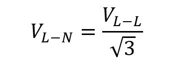
Explanation of Variables
- VLN (Line-to-Neutral Voltage): This is the voltage between a single phase and the system’s neutral point. It is often used for loads that are distributed across the three phases.
- VLL (Line-to-Line Voltage): This is the voltage between any two of the three phases. It is typically higher than VLN by a factor of √3, reflecting the phase differences.
- √3: This is a mathematical constant (approximately 1.732) that emerges from the geometry of an equilateral triangle representing the phase displacement in a three-phase system.
Detailed Real-Life Application Examples
In practical electrical engineering, conversion calculations are crucial for designing safe and efficient electrical systems. The following two examples illustrate common real-world applications involving voltage conversion.
Real-World Example 1: Industrial Motor Voltage Requirements
For an industrial facility, the specification sheet for a three-phase motor requires a line-to-neutral voltage of 230 V. The facility supplies power in a line-to-line system operating at 400 V. To ensure full compatibility, conduct a conversion to verify system suitability.
Using the conversion formula VLN = VLL / √3, substitute the facility’s line-to-line voltage into the formula. Calculation: VLN = 400 V / 1.732 ≈ 231 V. This result demonstrates that a supply of 400 V line-to-line provides approximately 231 V line-to-neutral, which is reasonably close to the required 230 V. Minor discrepancies may occur due to system tolerances, but this confirms compatibility.
- The motor was designed with a 230 V rating, and the calculated VLN from a 400 V supply meets this within acceptable margins.
- This conversion is vital for ensuring that the protective devices and motor controllers are correctly calibrated.
- In practice, any slight variance can be mitigated through voltage regulation measures.
The example demonstrates how proper conversion effectively ensures that the equipment functions within its rated parameters, promoting both safety and longevity.
Real-World Example 2: Commercial Building Electrical Distribution
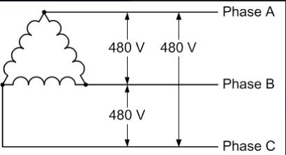
A commercial building’s electrical design specifies a three-phase distribution system where lighting and HVAC systems operate at 277 V line-to-neutral voltage. The available supply is at 480 V line-to-line. It is necessary to calculate the corresponding line-to-neutral voltage to gauge device compatibility and energy consumption efficiencies.
Utilize the conversion formula: VLN = 480 V / 1.732 ≈ 277.2 V. The result confirms that the supply voltage matches the equipment requirements almost exactly, ensuring efficient performance and minimal energy loss.
- This calculation is fundamental when planning emergency lighting circuits and HVAC control systems.
- Energy management systems rely on accurate voltage measurements to optimize consumption and ensure regulatory compliance.
- Confirming the voltage alignment helps prevent under-voltage or over-voltage scenarios which can damage sensitive equipment.
The conversion confirms the soundness of the design, providing confidence in the electrical distribution network’s capacity to handle diverse loads while maintaining performance standards.
How to convert Phase-Phase Voltage to Phase-Neutral in 1 step only:
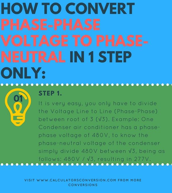
Step 1:
It is very easy, you only have to divide the Voltage Line to Line (Phase-Phase) between root of 3 (√3). Example: One Condenser air conditioner has a phase-phase voltage of 480V, to know the phase-neutral voltage of the condenser simply divide 480V between √3, being as follows: 480V / √3, resulting in 277V.
Examples of conversion of Phase-Phase to Phase-Neutral Voltage:
Example 1:
A stamping machine has a Line-to-Line voltage of 240Volts, how many Volts Linea Neutral has the stamping machine ?.
Answer: // To know the Linea-Neutral voltage of the press, the line-to-line voltage divided by three must be divided in the following way: V LN = 240V / √3, which will result in 138 Volts Neutral Line.
Example 2:
An insdustrial die cutter has a phase-phase voltage of 600Volts, how much will be the Phase-Neutral voltage that this machine will have?
Answer: // The solution is simple, you only have to divide 600Volts between the root of 3, in the following way: V LN = 600V / √3 = 346Voltios Phase-Neutral.
Example 3:
A coffee mill has a voltage of 13200Volts line to line, how much Linea to Neutral voltage will the mill have?
Answer: // To know the answer you should only divide the line-line voltage between √3, by means of the formula V LN = 13200V / √3, obtaining as result: 7621Voltios Linea-Neutro.
Phase-Phase to Phase-Neutral Voltage Conversion Table:
| How much Phase-Phase Voltage are | Equivalence Phase-Neutral Voltage |
| 190 Volts FF | Equivalent to 110 Volts Phase-Neutral |
| 208 Volts FF | 120 Volts FN |
| 220 Volts FF | 127 Volts FN |
| 230 Volts FF | 133 Volts FN |
| 240 Volts FF | 139 Volts FN |
| 380 Volts FF | 219 Volts FN |
| 400 Volts FF | 231 Volts FN |
| 415 Volts FF | 240 Volts FN |
| 440 Volts FF | 254 Volts FN |
| 460 Volts FF | 266 Volts FN |
| 480 Volts FF | 277 Volts FN |
| 500 Volts FF | 289 Volts FN |
| 600 Volts FF | 346 Volts FN |
| 4160 Volts FF | 2402 Volts FN |
| 11400 Volts FF | 6582 Volts FN |
| 13200 Volts FF | 7621 Volts FN |
| 15000 Volts FF | 8660 Volts FN |
| 34500 Volts FF | 19919 Volts FN |
| 44000 Volts FF | 25403 Volts FN |
| 57500 Volts FF | 33198 Volts FN |
| 66000 Volts FF | 38105 Volts FN |
| 115000 Volts FF | 66395 Volts FN |
How to use the Phase-Phase to Phase-Neutral Voltage calculator:
The first and only thing you must do is insert the line voltage to line you want to convert then you should click on the convert button and go.
Single-phase three-wire:
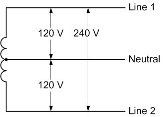
Also known as Edison system, divided or neutral phase with central intake. This is the most common residential service in North America. Line 1 to neutral and line 2 to neutral are used to power loads of 120 volts of lighting and electrical outlets. Line 1 to line 2 is used to feed 240 volt single-phase loads, such as a water heater or an air conditioner. Eye these lines in this case are not equivalent to Phases, are threads not Phases or lines.
Three-phase Wye Wye:
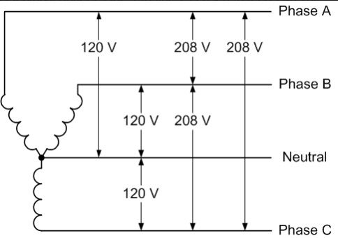
The most common commercial construction electrical service in North America is 120/208 volts in star, which is used to power 120 volt outlet loads, lighting and smaller HVAC systems.
In larger installations, the voltage is 277/480 volts and is used to supply a phase-neutral voltage of 277 volts of illumination and higher HVAC loads. In western Canada 347 / 600V is more common.
Three-phase three-wire Delta:
It is mainly used in industrial facilities to provide power for three-phase motor loads and utility utility power distribution applications. Rated service voltages of 240, 400, 480, 600 and higher are typical.
Implementation in Real-World Design Scenarios
Beyond straightforward conversions, engineers need to integrate voltage conversion calculations into broader system designs that include protection coordination, energy distribution management, and compliance with local and international electrical standards.
For example, in industrial plants, the selection of transformers, switchgear, and protective relays depends not only on the nominal voltage levels but also on the accuracy of conversion between line-to-line and line-to-neutral measurements. Designers use these voltage relationships to ensure that each component is correctly rated to prevent overloading and potential failures.
Transformer Selection
A transformer in a three-phase network is often rated based on its ability to handle both line-to-line and line-to-neutral voltages. When selecting a transformer, the engineer must check that the secondary winding delivers the correct voltage level after applying the √3 conversion factor.
For transformers rated in kilovolt-amperes (kVA), the relationship between the input and output voltages is critical. Using the formulas and tables provided, engineers quickly verify that the transformer will operate efficiently under load and will deliver safe and reliable performance in real-world installations.
Switchgear and Protective Device Coordination
The coordination of protective devices such as circuit breakers and fuses is based on precise voltage measurements. A miscalculation in the conversion can lead to the selection of devices that either trip too frequently or fail to trip during a fault.
Therefore, the calculation of line-to-neutral voltage from a known line-to-line voltage is not just an academic exercise but a vital step in ensuring that protective devices are correctly rated. Adhering to standards such as the National Electrical Code (NEC) and IEC standards further reinforces the need for meticulous voltage calculations.
Industry Standards and Best Practices
Compliance with international electrical standards is paramount in electrical engineering design. Organizations such as the IEEE, IEC, and NEC provide guidelines that incorporate the conversion formulas discussed above.
Adhering to these standards ensures not only the safety and reliability of electrical installations but also their efficiency and longevity. Best practices include double-checking conversions, using calibrated measurement instruments, and applying conservative design margins in critical applications.
Updated Regulations and Guidelines
Electrical standards are continuously revised to incorporate new technological advancements and industry feedback. It is essential for engineers to stay informed about the latest revisions to avoid miscalculations that could compromise system safety.
Resources like the IEEE Xplore, IEC official website, and the National Electrical Code are excellent external links to validate the common practices highlighted in this article. Regular training sessions and professional workshops further ensure that field engineers are up-to-date on the best practices regarding voltage conversions.
Frequently Asked Questions
Q: Are these conversion methods used globally?
A: Yes, the principles are universal in three-phase electrical systems, applicable in both industrial and commercial power distribution networks.
Q: What is the significance of the √3 factor in voltage conversion?
A: The √3 factor arises from the geometry of three-phase systems, representing the phase displacement of 120° between the phases.
Q: Can these formulas be applied to unbalanced systems?
A: The formulas assume a balanced system. For unbalanced loads, additional factors must be considered, often requiring specialized software analysis.
Q: How do voltage drops influence these calculations?
A: Voltage drops, particularly in long cable runs, need to be calculated separately and subtracted from the ideal voltage obtained from conversion formulas.