Arc flash hazards are among the most dangerous threats for personnel working on energized electrical equipment.
NFPA 70E defines procedures, formulas, and PPE to mitigate risks and ensure safe electrical work environments.
Arc Flash Protection Calculator (NFPA 70E / IEEE 1584)
Common Arc Flash Calculation Values Based on NFPA 70E
The following table includes frequently used parameters and typical values encountered during arc flash analysis. These values help engineers establish baselines for initial assessments.
Table 1: Common Arc Flash Parameters and Ranges
| Parameter | Symbol | Typical Values / Range | Units | Notes |
|---|---|---|---|---|
| System Voltage | V | 208, 240, 480, 600, 4160, 13,800 | Volts (V) | Phase-to-phase voltage |
| Bolted Fault Current | Ibf | 5,000 – 100,000 | Amperes (A) | At equipment terminals |
| Working Distance | D | 12, 18, 24 | Inches | Based on equipment type (e.g., 18” for switchgear) |
| Arc Duration | t | 0.03 – 2.0 | Seconds (s) | Determined by protection device clearing time |
| Equipment Type | — | Switchgear, MCC, panelboards, disconnects | — | Different configurations affect arc energy |
| Grounding Type | — | Ungrounded, Solid Grounded, High Resistance | — | Influences the magnitude of fault current |
| Arc Flash Boundary | Afb | 12 – 240 | Inches | Depends on incident energy threshold (typically 1.2 cal/cm²) |
| Incident Energy (at 18″) | IE | 0.5 – 40+ | cal/cm² | Determines required PPE level |
| Minimum PPE Category | — | 1 to 4 | — | Based on incident energy |
Essential Arc Flash Formulas per NFPA 70E
NFPA 70E doesn’t mandate a single formula but refers to IEEE Std. 1584-2018 for detailed arc flash calculations. Below are the primary equations used:
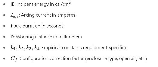
1. Incident Energy (IE) Equation — IEEE 1584-2018 (Simplified Empirical Model)

Reference: IEEE 1584 Guide for Performing Arc-Flash Hazard Calculations
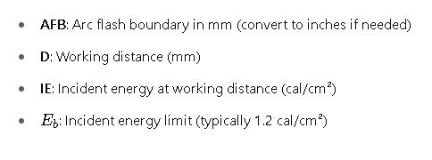
2. Arc Flash Boundary (AFB) Equation
Where:

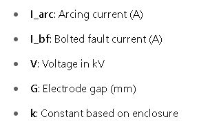
3. Arcing Current (IEEE 1584 Empirical)


Detailed Explanation of Variables and Typical Values
| Variable | Description | Typical Value or Range |
|---|---|---|
| I_bf | Bolted fault current | 10,000 – 65,000 A |
| I_arc | Arcing current | 40% – 90% of I_bf |
| V | System voltage (phase-phase) | 0.208 – 13.8 kV |
| G | Electrode gap (distance between conductors) | 13 mm (0.5″) to 75 mm (3″) |
| t | Arc duration | 0.1 – 2.0 s |
| D | Working distance | 455 mm (18 inches) typical |
| IE | Incident energy | 1.2 – 40 cal/cm² |
| E_b | Boundary energy limit | 1.2 cal/cm² |
Real-World Application Example #1: 480V MCC Panel in Industrial Plant
Scenario:
- Voltage: 480 V
- Bolted Fault Current: 25,000 A
- Working Distance: 18 inches
- Arc Duration: 0.2 seconds
- Enclosure Type: MCC (Metal Clad)
Step 1: Estimate Arcing Current
Using IEEE 1584:
Step 2: Calculate Incident Energy
Assume:
Step 3: Determine PPE Category
According to NFPA 70E PPE Table:
- Category 3 (8 cal/cm² arc-rated suit required)
Step 4: Arc Flash Boundary
Real-World Application Example #2: 13.8kV Switchgear in Utility Substation
Scenario:
- Voltage: 13.8 kV
- Bolted Fault Current: 20,000 A
- Working Distance: 36 inches (914 mm)
- Arc Duration: 0.5 s
- Enclosure Type: Medium-voltage cubicle
Step 1: Arcing Current Estimate
IEEE 1584 model:
Step 2: Incident Energy
Step 3: PPE Required
- Category 2 PPE (minimum 8 cal/cm² suit)
Step 4: Arc Flash Boundary
Important Considerations from NFPA 70E
- Arc Flash PPE Categories: Defined in NFPA 70E Table 130.7(C)(15)(c)
- Risk Assessment Requirements: Mandatory per Article 130.5 of NFPA 70E
- Labeling Requirements: Equipment must be labeled with arc flash information, including:
- Nominal voltage
- Arc flash boundary
- Incident energy (or PPE category)
- Working Distance: Set based on the expected location of the worker’s torso or face
- Short-Circuit and Coordination Study: Needed before arc flash study
Authoritative References
- NFPA 70E Standard for Electrical Safety in the Workplace (Official)
- IEEE Std 1584-2018 Guide for Arc Flash Hazard Calculations
- OSHA Regulations – Electrical Safety (29 CFR 1910 Subpart S)
Arc Flash PPE Categories and Required Protection Levels
Proper selection of Personal Protective Equipment (PPE) is critical in reducing injuries during arc flash events. NFPA 70E defines four PPE categories, each associated with a specific incident energy level.
Table 2: PPE Categories per NFPA 70E Table 130.7(C)(15)(c)
| PPE Category | Minimum Arc Rating | Typical Equipment | PPE Required |
|---|---|---|---|
| Category 1 | 4 cal/cm² | Control panels <240V | Arc-rated shirt and pants, safety glasses, face shield, rubber gloves |
| Category 2 | 8 cal/cm² | Panelboards 240-600V | Arc-rated suit, balaclava, hard hat, voltage-rated gloves, hearing protection |
| Category 3 | 25 cal/cm² | Switchgear 600–1kV | Arc-rated coverall or flash suit, hood, gloves, insulated tools |
| Category 4 | 40 cal/cm² | MV Switchgear >1kV | Arc-rated flash suit with hood, gloves, boots, double-layer protection |
PPE must match or exceed the calculated incident energy level. Labels on equipment must state either:
- The actual calculated incident energy (e.g., 6.8 cal/cm²), or
- The corresponding PPE category.
Arc Flash Risk Assessment Process (per NFPA 70E Article 130.5)
NFPA 70E requires a formal arc flash risk assessment with the following steps:
- Collect system data: Equipment ratings, protective device settings, conductor sizes.
- Perform short-circuit and coordination studies.
- Determine bolted fault current at each equipment bus.
- Estimate arcing current and arc duration using IEEE 1584 or simplified methods.
- Calculate incident energy and arc flash boundary.
- Assign PPE category or specify cal/cm² on arc flash labels.
- Label all equipment that may require energized work.
- Review and update the study every 5 years or when modifications are made.
Common Software Used in Arc Flash Studies
| Software | Key Features | Usage Example |
|---|---|---|
| SKM Power Tools | IEEE 1584 engine, coordination, short-circuit, arc flash | Industrial plants, utilities |
| ETAP | Arc flash labels, PPE reports, advanced visualization | Data centers, substations |
| EasyPower | One-line diagrams, rapid arc flash study | Commercial facilities |
| ARCAD ArcCalc | Simplified IEEE-based calculator | Small shops, quick assessments |
Enhancing Arc Flash Protection Beyond PPE
While PPE mitigates injury, the most effective strategy is reducing incident energy through engineering controls:
Energy Reduction Techniques:
- Current-limiting fuses: Minimize arc duration.
- Zone-selective interlocking (ZSI): Improve relay coordination.
- Arc-flash relay systems: Detect and interrupt arcs rapidly (<50ms).
- Maintenance switches: Temporarily lower protection settings during work.
- Remote racking: Isolate workers from arc hazard zones.
Maintenance Mode Example
In a switchgear setup:
- Normal clearing time: 0.5s → IE = 9.2 cal/cm²
- Maintenance mode: 0.07s → IE = 1.4 cal/cm² (Category 1)
Result: Worker shifts from a 40 cal suit to light PPE.
Arc Flash Label Sample Format (per NFPA 70E Article 130.5(H))
A compliant label must include:
| Label Element | Example Value |
|---|---|
| Nominal System Voltage | 480V |
| Arc Flash Boundary | 36 inches |
| Incident Energy Level | 6.8 cal/cm² |
| PPE Category | Category 3 |
| Working Distance | 18 inches |
| Date of Assessment | June 2025 |
Labels must be updated when system changes affect the calculation.
FAQ: Arc Flash Calculation According to NFPA 70E
Q1: How often must arc flash studies be updated?
A: Every 5 years, or whenever changes in the electrical system could affect results.
Q2: Can I use the PPE Category method instead of incident energy?
A: Yes, but only when all conditions in NFPA 70E tables are met exactly. Otherwise, detailed energy analysis is required.
Q3: What’s the minimum arc flash boundary?
A: The default threshold is 1.2 cal/cm², which can result in boundaries of 12–60+ inches depending on conditions.
Q4: What are the penalties for non-compliance?
A: OSHA can issue citations for NFPA 70E violations under the General Duty Clause. Penalties range from warnings to $150,000+ fines.
Final Thoughts on Arc Flash Calculation Best Practices
Performing a compliant and effective arc flash hazard analysis involves:
- Precise data gathering
- Adherence to NFPA 70E and IEEE 1584
- Clear labeling and documentation
- Training personnel in safe work practices
- Investing in PPE and energy-reducing technologies
Even a modest arc flash event can lead to life-threatening injuries and millions in damage. Proper calculation, PPE, and engineering controls are non-negotiable in any modern electrical safety program.


