This technical guide explains VA to watts conversion fundamentals for electrical systems and equipment sizing.
Engineers require precise VA-to-watt calculators to assess load, efficiency, power factor, and safety margins accurately.
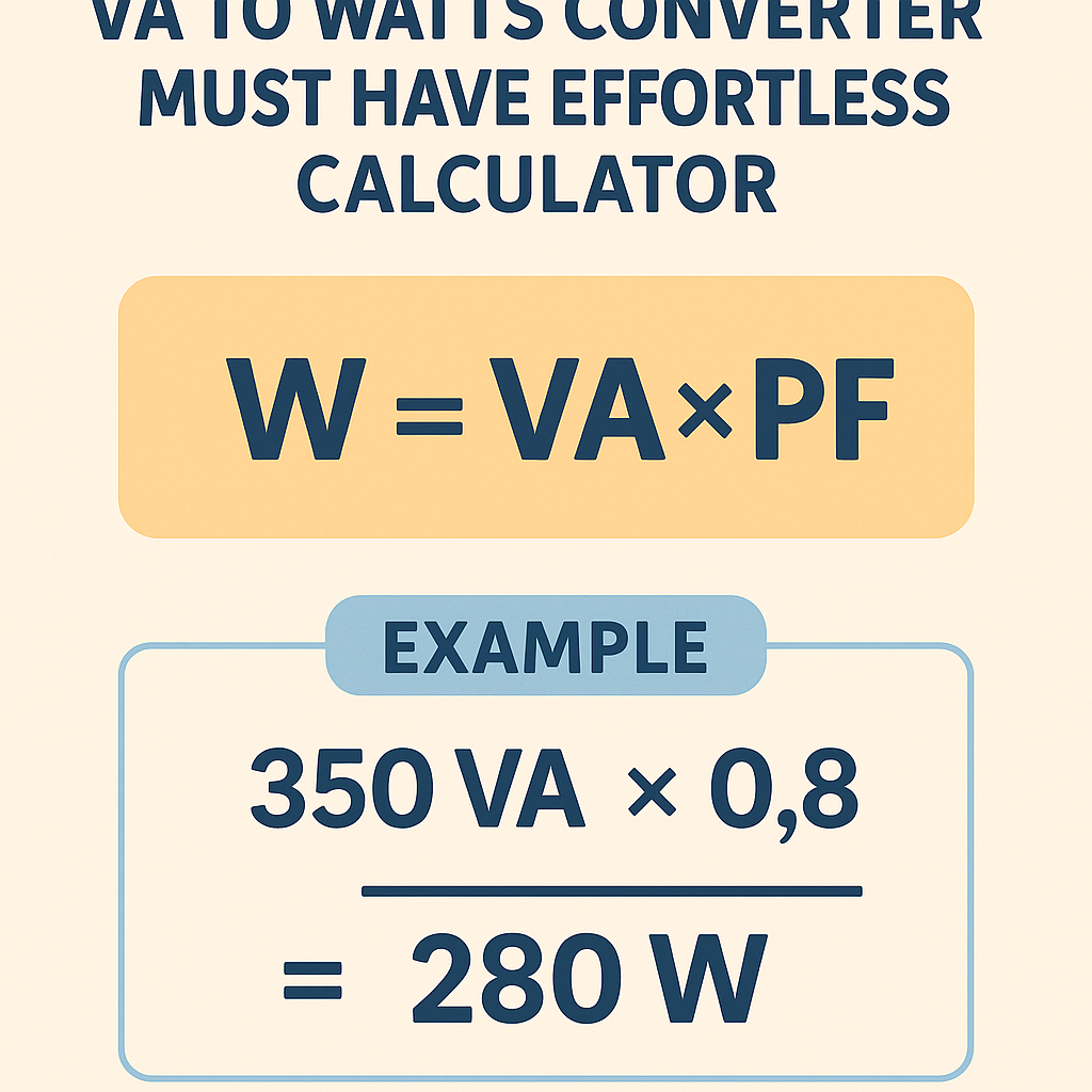
VA to Watts Converter — Precise Engineering Calculator
Fundamental Equations and Electrical Theory for VA-to-Watts Conversion
The core relationship between apparent power (VA) and real power (W) is determined by the power factor. Use the following basic formulas when converting between units for balanced and unbalanced circuits.
Basic single-phase relationship
- Where V is the RMS voltage (volts).
- I is the RMS current (amperes).
- Power Factor (PF) is dimensionless, range 0–1 (cos φ for sinusoidal systems).
- Apparent Power (VA) is V × I for single-phase systems.
Three-phase (balanced) relationship
Where V_LL is line-to-line RMS voltage (volts) and I_L is line current (amperes).
- For delta or wye connections with balanced loads, use the √3 formula for total real power.
- Per-phase real power is P_phase = V_phase × I_phase × PF.
Formulas, variable explanations, and typical values
Explicit formulas for quick reference (use exactly these forms when programming a calculator):
Single-phase:
Three-phase (balanced):
To compute current from VA or W:
Variable definitions and typical engineering ranges:
- V (RMS voltage): 110–240 V (residential), 400–480 V (industrial). Typical: 230 V or 400 V.
- I (RMS current): Depends on load; compute using formulas above.
- VA (apparent power): Rated for transformers, UPSs, and gensets. Typical units: VA, kVA.
- W (real power): Energy converting to work or heat; units watts (W) or kilowatts (kW).
- PF (power factor): Resistive loads ≈ 1.0, induction motors 0.6–0.95, switch-mode power supplies 0.6–0.99 with correction.
Design considerations for an effortless VA-to-Watts calculator
A usable converter must handle units, phases, PF, and provide clear current sizing results. Feature checklist:
- Input options: VA, W, V (line or phase), PF, system type (single/three-phase).
- Unit conversions: VA ↔ kVA; W ↔ kW; V RMS selection for regionally typical nominal voltages.
- Automatic PF default selection with editable values—include common presets.
- Display derived quantities: current per phase, suggested conductor ampacity, breaker size estimation (rounded standard sizes), and apparent power margin.
- Validation and warnings: PF outside 0–1, overloaded circuits, and unrealistic voltage values.
- Traceable calculations: show each step so engineers can audit results.
Calculator accuracy and measurement uncertainty
Engineering calculators should propagate input uncertainties to output uncertainty using standard error propagation rules for multiplication and division.
- σ denotes standard uncertainty of the variable.
- When PF is measured with limited resolution, uncertainty can dominate for near-unity PF.
- Datasheet specs for meters and transducers should be applied (e.g., ±0.5% accuracy, phase error).
Extensive tables with common values and conversions
| Device / Load | Typical VA Rating | Typical PF | Calculated Real Power (W) | Notes |
|---|---|---|---|---|
| Incandescent lamp 60 W | 60 VA | 1.00 | 60 W | Resistive load, PF≈1 |
| LED lamp 10 W | 12 VA | 0.90 | 10.8 W | Driver losses and distortion reduce PF |
| Desktop PC (with PSU) | 600 VA | 0.65 | 390 W | SMPS without PFC |
| Server blade (data center) | 1200 VA | 0.95 | 1140 W | High-efficiency PSUs with PFC |
| Air conditioner (residential) | 3000 VA | 0.85 | 2550 W | Compressor startup requires additional inrush capacity |
| Three-phase motor (10 kVA) | 10000 VA | 0.85 | 8500 W | Full-load PF typical for induction motor |
| UPS (2 kVA) | 2000 VA | 0.8 | 1600 W | Manufacturer rating often shows VA and PF |
| Transformers (rating) | 50000 VA | 0.95 | 47500 W | Supply-side PF assumptions for sizing |
| Nominal Voltage | Single-phase I (A) for 1 kVA at PF=1 | Three-phase I (A) for 1 kVA at PF=1 | Notes |
|---|---|---|---|
| 120 V | 8.333 | 4.808 | North American lighting circuits |
| 230 V | 4.348 | 2.506 | Common single-phase European service |
| 400 V (3ϕ) | N/A | 1.443 | Standard industrial distribution |
| 480 V (3ϕ) | N/A | 1.205 | North American industrial systems |
Practical measurement and instrumentation notes
When creating or using an effortless converter, interface with measurement instruments appropriately. These are essential guidelines:
- Use True RMS meters for non-sinusoidal currents and voltages. Averaging meters give incorrect PF and W for distorted waveforms.
- Prefer instruments that measure real power directly (W) and apparent power (VA) concurrently to compute PF = W / VA.
- For three-phase systems, use a three-phase power analyzer to avoid error in unbalanced conditions. Single-phase clamps on each phase require synchronized sampling for correct total W and VA.
- Be aware of harmonic distortion: harmonic currents increase apparent power with little increase in useful real power, lowering PF (displacement and distortion PF concepts).
Harmonic considerations and corrected power factor
In presence of harmonics, apparent power S is composed of fundamental apparent power and harmonic components. The IEEE and IEC literature differentiate between displacement PF and true PF (includes distortion).
Basic corrective equation when harmonics are present (qualitative):
Therefore, accurate converters should accept harmonic content or measured S and W rather than estimating PF solely from cos φ if waveform distortion exists.
Examples with step-by-step solutions
Example 1 — Single-phase UPS and load assessment
Problem statement: A small office UPS is rated 3000 VA. The manufacturer states the UPS provides PF = 0.9. Determine the usable continuous real power (W), the maximum continuous current on a 230 V supply, and recommend an upstream breaker size with 125% continuous rating compliance.
Step 1 — Real power calculation:
Step 2 — Current on 230 V single-phase:
Note: Use VA to compute conductor current because the UPS loads apparent power on the supply. Alternatively compute I from real power considering PF:
I_from_W = W / (V × PF) = 2700 / (230 × 0.9) = 2700 / 207 = 13.043 A (same result).
Step 3 — Upstream breaker sizing (continuous load guidance):
- Continuous load is defined as load that lasts for three hours or more; conservative design uses 125% of continuous current.
- Required breaker rating = I × 1.25 = 13.043 × 1.25 ≈ 16.304 A.
- Select nearest standard breaker size: 20 A.
Solution summary:
- Real power available: 2700 W.
- Supply current: ≈13.04 A.
- Recommended breaker: 20 A (after verifying conductor ampacity and ambient derating).
Example 2 — Three-phase motor load and conductor sizing
Problem statement: A factory installs a new motor with nameplate 50 kVA at PF 0.88 on a 400 V three-phase distribution. Calculate real power, line current, and suggest an appropriate 80% continuous current rating for a protective device if motor is expected to run continuously.
Step 1 — Real power calculation:
Step 2 — Line current calculation using balanced three-phase formula:
Step 3 — Protective device sizing (continuous):
- If considered continuous, protective device must be sized at 125% of continuous current for thermal limits, or follow local code. Alternative approach: use 80% rule for breaker trip settings—here we show both.
- Required ampacity = I_L × 1.25 = 72.18 × 1.25 ≈ 90.23 A — conductor ampacity check required.
- Breaker selection: NEMA/IEC practices vary. For continuous loads, you may select breaker with continuous rating above 90.23 A; choose standard 100 A breaker, confirm coordination and inrush capability.
Solution summary:
- Real power: 44.0 kW.
- Line current: ≈72.2 A.
- Recommended protective device nominal: 100 A (subject to detailed coordination and code compliance).
Example 3 — Sizing VA for a desired real output and correcting PF (additional practical)
Problem statement: A data center requires 25 kW of continuous real power. The expected power factor of the server equipment is 0.95. Determine required UPS VA capacity and the corresponding three-phase current on 400 V supply.
Step 1 — Required VA capacity:
Step 2 — Line current (three-phase):
Design notes:
- Select UPS with available kVA rating above 26.316 kVA to allow margin; choose 30 kVA to cover future expansion and harmonic heating.
- Confirm UPS inverter continuous current capability and harmonic performance; many UPS ratings assume a specific PF (e.g., 0.9), so verify manufacturer datasheets.
Tables: Common PF values and sizing look-up
| Load Type | Typical PF Range | Design PF Use | Impact on VA vs. W |
|---|---|---|---|
| Resistive heating (heaters, ovens) | 0.99–1.00 | 1.00 | VA ≈ W (no PF penalty) |
| Incandescent lighting | 0.95–1.00 | 1.00 | Minimal difference |
| LED lighting (with driver) | 0.6–0.98 | 0.90 | Design for higher VA margin |
| SMPS (no PFC) | 0.55–0.75 | 0.65 | Significant VA oversizing |
| Induction motors (small to large) | 0.6–0.95 | 0.85 | Consider inrush currents for short-term sizing |
| Power electronics with active PFC | 0.95–0.99 | 0.98 | Near unity, reduces VA requirements |
Regulatory, normative references and authoritative resources
Use these standards and authority sources when designing conversions, specifying equipment, and creating calculators:
- IEC 60038 — "IEC Standard Voltages" (defines common nominal voltages worldwide). More: https://www.iec.ch/
- IEEE Std 141 (Red Book) — "Electrical Power Distribution for Industrial Plants" (system design and analysis guidance). More: https://www.ieee.org/
- IEEE Std 519 — "Recommended Practices and Requirements for Harmonic Control in Electrical Power Systems" (harmonic limits and mitigation). More: https://standards.ieee.org/
- NIST — National Institute of Standards and Technology guidelines on electrical measurements and instrument calibration. More: https://www.nist.gov/
- U.S. Department of Energy (DOE) — Efficiency and power electronics resources, helpful for practical PF correction strategies. More: https://www.energy.gov/
- Local electrical codes (NEC/NFPA 70 in the USA, IEC regulations in many jurisdictions) — mandatory for conductor and protective device sizing. Refer to your jurisdiction-specific code.
Implementation notes for an effortless calculator UI/UX
To make a converter genuinely effortless for engineers and technicians, prioritize the following UX features:
- Clear input semantics: label whether V is line-to-line or line-to-neutral and whether VA refers to per-phase or total kVA.
- Preset regional nominal voltages with editable custom values.
- Provide PF presets with short explanations (e.g., "motors: 0.85 typical").
- Show both VA→W and W→VA pathways, and automatically compute related current and breaker suggestions.
- Include safety warnings: continuous load derating, conductor temperature correction factors, and inrush concerns for motors.
- Allow exporting of calculation trace and assumptions for audit and sign-off purposes.
- Provide toggles for single-phase and three-phase formulas and show step-by-step math for validation.
Testing, verification, and documentation best practices
Ensure the calculator is validated against known values and industry-standard test cases. Recommended verification steps:
- Unit tests for formula implementations (single-phase and three-phase).
- Cross-check computed values with physical measurements from power analyzers across a representative set of loads (resistive, inductive, nonlinear).
- Calibration and verification of meter input assumptions (RMS, crest factor handling).
- Document assumptions: PF semantics, rounding rules, safety margins, and code references used in sizing rules.
- Provide links to referenced standards within the tool or documentation for traceability.
Common pitfalls and how the effortless calculator avoids them
- Confusing VA with W — the calculator should explicitly ask for PF or measured W and VA to avoid assumptions.
- Using RMS average meters for distorted waveforms — specify True RMS requirement and include a warning.
- Neglecting harmonics — include a harmonic-aware mode that uses measured S and W rather than estimated PF from displacement only.
- Misinterpreting three-phase voltages — provide clear selection for V_LL versus V_LN.
- Incorrect breaker/conductor sizing — implement code-aware multipliers or allow users to select jurisdiction code rules.
Maintenance, calibration, and periodic review
For tools used in procurement or safety-critical decisions, perform periodic review and calibration:
- Annually review default PF presets against current equipment data sheets.
- Validate rounding rules and unit conversions after any software update.
- Ensure links to external standards are current and update normative citations as standards are revised.
- Retain traceable logs of each calculation for at least the lifecycle required by the project or facility.
Further reading and authoritative links
- IEC — International Electrotechnical Commission: https://www.iec.ch/
- IEEE Standards and recommended practice documents: https://standards.ieee.org/
- NIST — Measurement and calibration resources: https://www.nist.gov/
- U.S. Department of Energy — Power electronics and efficiency: https://www.energy.gov/
- NFPA (National Fire Protection Association) / NEC resources on conductor and breaker sizing: https://www.nfpa.org/
Key takeaways for engineering practice
- Always treat VA and W as distinct quantities; PF links them.
- Design converters to accept measured S and W when harmonics exist rather than assuming sinusoidal conditions.
- Provide traceable calculations with clear variable definitions and use standardized unit conversions.
- Include regional voltage presets, continuous load derating, and standard breaker/conductor rounding to aid practical design.
- Reference and align with IEC/IEEE/NIST/Local code standards when sizing equipment and protective devices.
Final engineering notes (operational and procurement guidance)
When procuring equipment (transformers, UPS, generators), specify both VA (kVA) and W (kW) requirements with expected PF and harmonic content. Ask manufacturers for performance curves including PF at loads, harmonic current injections, and continuous vs. peak ratings. A well-designed VA-to-watts converter with the features described will drastically reduce specification errors, ensure proper protection sizing, and improve system reliability.
For traceable engineering decisions, accompany each calculation with the chosen standards, measurement assumptions, and a signed review. This ensures compliance with safety codes and simplifies commissioning and audits.
References
- IEC 60038 — Standard Voltages: https://www.iec.ch/
- IEEE Std 519 — Harmonic Control in Power Systems: https://standards.ieee.org/
- IEEE Std 141 — Power Distribution for Industrial Plants: https://standards.ieee.org/
- NIST Calibration Services and Guides: https://www.nist.gov/
- U.S. Department of Energy — Electrical System Efficiency: https://www.energy.gov/
- NFPA 70 (NEC) — National Electrical Code (refer to local code editions for conductor and protective device sizing): https://www.nfpa.org/