This technical guide explains converting kilowatts to amperes accurately for electrical system design and safety.
Engineers require precise formulas, examples, and normative references to ensure compliant installations under varied loads.
kW to Amps Conversion Calculator (Load Current from Active Power)
Formulas used
The calculator converts active power in kilowatts (kW) to RMS current in amperes (A) using standard AC power relationships.
- Single-phase AC:
Current (A) = P(kW) × 1000 / (V(V) × power factor × efficiency) - Three-phase AC:
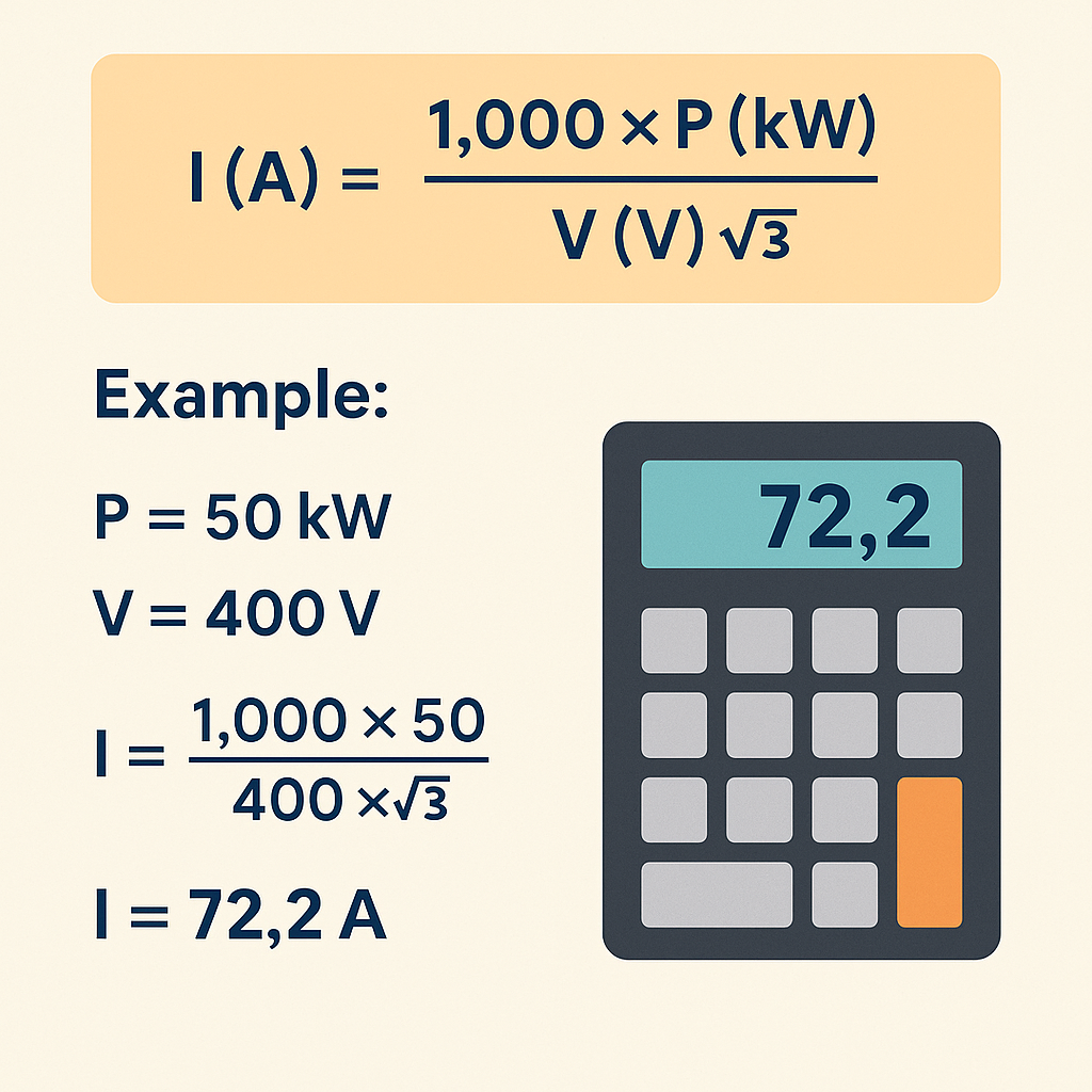
Current (A) = P(kW) × 1000 / (√3 × V(V) × power factor × efficiency)
Where:
- P(kW): active (real) power in kilowatts.
- V(V): line voltage (RMS) in volts. For three-phase systems this is the line-to-line voltage.
- Power factor (cos φ): dimensionless, between 0 and 1. If not specified, the calculator assumes power factor = 1.0.
- Efficiency: dimensionless ratio between 0 and 1 (input as percent in the form). If not specified, the calculator assumes efficiency = 1.0 (100 %).
Quick reference table (typical full-load currents)
| Power (kW) | Voltage (V) | Phase | Assumed power factor | Approx. current (A) |
|---|---|---|---|---|
| 1.0 | 230 | Single-phase | 1.0 | ≈ 4.3 A |
| 2.0 | 230 | Single-phase | 0.8 | ≈ 10.9 A |
| 5.0 | 400 | Three-phase | 0.8 | ≈ 9.0 A |
| 15.0 | 400 | Three-phase | 0.8 | ≈ 27.1 A |
| 30.0 | 400 | Three-phase | 0.8 | ≈ 54.1 A |
| 50.0 | 480 | Three-phase | 0.85 | ≈ 70.7 A |
Technical FAQ
- Which voltage should I enter in the calculator?
- Use the nominal RMS line voltage of the supply. For three-phase systems this is the line-to-line voltage (for example 400 V or 480 V). For single-phase loads use the supplied voltage between live and neutral or between the two live conductors, depending on the system configuration.
- What power factor should I assume if it is not specified on the nameplate?
- If the power factor is unknown, a value between 0.8 and 0.9 is typical for standard induction motors, and near 1.0 for purely resistive loads such as heating elements. The calculator allows you to leave the field empty; in that case it assumes power factor = 1.0, which gives the minimum current for the specified kW.
- Does this calculator give kW or kVA, and what is the difference?
- The input is active power in kW and the output is current in amperes. Apparent power in kVA can be obtained by dividing kW by the power factor. kW represents useful (real) power, while kVA includes both real and reactive components.
- Can I use the result directly to size conductors or protective devices?
- The result provides an approximate full-load current under the specified assumptions. For conductor sizing, protective device selection and coordination, you must apply the relevant installation standards (such as IEC 60364 or the applicable national code), considering derating factors, ambient conditions and starting currents.
Understanding kW to Amps Conversion Principles
Conversion from kilowatts (kW) to amperes (A) is fundamental for sizing conductors, protection, and equipment. Power (kW) is a real-power quantity; current (A) depends on applied voltage, number of phases, and power factor. Accurate conversion reduces oversizing, avoids overheating, and ensures compliance with standards.
Basic power relationships
Key equations used in practice are:
- Single-phase: I = (P × 1000) / (V × PF)
- Three-phase: I = (P × 1000) / (√3 × V × PF)
Where P is active power in kilowatts, V is line-to-line voltage in volts, PF is power factor (unitless), and I is line current in amperes. Use 1.732 for √3 when calculating three-phase values.
Derivation and variable definitions
Derive formulas from instantaneous power relations: P (W) = V × I × PF for single-phase. For three-phase balanced systems, P (W) = √3 × V × I × PF.
Variables explained with typical ranges
- P (kilowatts, kW): active (real) power. Typical ranges: small appliances 0.1–5 kW, HVAC/motors 5–500 kW, utility plants >500 kW.
- V (volts, V): operational line voltage. Common values: single-phase 120 V, 230 V, 240 V, 277 V; three-phase 208 V, 380–415 V, 400 V, 460 V, 480 V, 600 V.
- PF (power factor): cosine of phase angle between voltage and current. Typical values: resistive loads PF ≈ 1.0, motors 0.7–0.95 (depending on loading), electronic drives 0.9–0.99 with correction.
- I (amperes, A): line current to be calculated for conductor and protection sizing.
- √3: square root of three ≈ 1.732, used for balanced three-phase systems.
Formulas presented as inline expressions
Single-phase direct formula:
Three-phase direct formula:
Note: Multiply kW by 1000 to convert to watts, since 1 kW = 1000 W.
Practical factors affecting conversion accuracy
- Power factor: For motors and inductive loads, assume worst-case PF for protection coordination unless measurements are available.
- Load diversity and duty cycle: Continuous loads per many codes require conductor sizing to 125% of continuous current. Check local code rules.
- Voltage unbalance: Deviations from nominal voltage alter current; use measured operating voltage.
- Ambient temperature and conductor bundling: Ampacity derating may be required; perform ampacity calculations after converting kW to A.
- Startup/inrush currents: Motors and some supplies have large inrush; protective devices must accommodate or coordinate with soft-start/limiters.
Extensive conversion tables — single-phase
| Power (kW) | 120 V, PF=1.0 (A) | 230 V, PF=1.0 (A) | 240 V, PF=1.0 (A) | 120 V, PF=0.8 (A) | 230 V, PF=0.8 (A) | 240 V, PF=0.8 (A) |
|---|---|---|---|---|---|---|
| 0.5 | 4.17 | 2.17 | 2.08 | 5.21 | 2.71 | 2.60 |
| 1.0 | 8.33 | 4.35 | 4.17 | 10.42 | 5.42 | 5.21 |
| 2.0 | 16.67 | 8.70 | 8.33 | 20.83 | 10.83 | 10.42 |
| 3.5 | 29.17 | 15.22 | 14.58 | 36.46 | 19.03 | 18.23 |
| 5.0 | 41.67 | 21.74 | 20.83 | 52.08 | 27.17 | 26.04 |
| 10.0 | 83.33 | 43.48 | 41.67 | 104.17 | 54.35 | 52.08 |
| 20.0 | 166.67 | 86.96 | 83.33 | 208.33 | 108.70 | 104.17 |
| 50.0 | 416.67 | 217.39 | 208.33 | 520.83 | 271.74 | 260.42 |
| 100.0 | 833.33 | 434.78 | 416.67 | 1041.67 | 543.48 | 520.83 |
Table notes: Values computed with I = (P×1000)/(V×PF). Entries present two PF scenarios common in field estimates.
Extensive conversion tables — three-phase
| Power (kW) | 208 V, PF=0.9 (A) | 400 V, PF=0.9 (A) | 415 V, PF=0.9 (A) | 460 V, PF=0.9 (A) | 480 V, PF=0.9 (A) | 600 V, PF=0.9 (A) |
|---|---|---|---|---|---|---|
| 5 | 15.79 | 8.03 | 7.75 | 6.98 | 6.69 | 5.35 |
| 10 | 31.58 | 16.05 | 15.50 | 13.97 | 13.38 | 10.70 |
| 20 | 63.16 | 32.10 | 31.01 | 27.94 | 26.77 | 21.39 |
| 50 | 157.89 | 80.24 | 77.52 | 69.85 | 66.92 | 53.48 |
| 100 | 315.79 | 160.48 | 155.04 | 139.70 | 133.85 | 106.96 |
| 150 | 473.68 | 240.72 | 232.56 | 209.55 | 200.78 | 160.45 |
| 250 | 789.47 | 401.19 | 387.61 | 349.25 | 334.62 | 267.39 |
| 500 | 1578.95 | 802.38 | 775.22 | 698.50 | 669.23 | 534.78 |
Table computation uses I = (P×1000)/(1.732×V×PF) with PF=0.9 typical for heavily loaded industrial motors.
Step-by-step worked examples
Example 1 — Single-phase residential heater
Problem statement: A domestic electric heater rated at 3.5 kW will be connected to a single-phase 230 V supply. Determine the current and suitable protective considerations. Assume PF = 1.0 for a resistive heater.
- Identify parameters:
- P = 3.5 kW
- V = 230 V (single-phase)
- PF = 1.0
- Apply the single-phase formula:
I = (P × 1000) / (V × PF)I = (3.5 × 1000) / (230 × 1.0)I = 3500 / 230 = 15.217 A (rounded to 15.22 A)
- Practical selection:
- Per many installation rules continuous loads require 125% sizing: 15.22 A × 1.25 = 19.03 A.
- Choose a circuit breaker and conductor rated above this value, e.g., a 20 A breaker with 2.5 mm² copper conductor may be acceptable per local code ampacity tables (verify ambient/derating).
- Notes:
- Verify local code for continuous load definition (NEC defines continuous >3 hours).
- If installed in conduit with multiple conductors, apply ampacity derating per applicable standard.
Example 2 — Three-phase industrial motor
Problem statement: A factory motor has nameplate 150 kW, connected to a 400 V three-phase system. Nameplate PF is 0.88. Calculate expected full-load current and recommend initial conductor and protection sizing steps.
- Identify parameters:
- P = 150 kW
- V = 400 V (line-to-line)
- PF = 0.88
- Apply the three-phase formula:
I = (P × 1000) / (1.732 × V × PF)I = (150 × 1000) / (1.732 × 400 × 0.88)Denominator = 1.732 × 400 × 0.88 = 1.732 × 352 = 609.664I = 150000 / 609.664 ≈ 246.08 A
- Continuous and starting considerations:
- If motor is continuous duty, apply required service factor as per local code (e.g., NEC often requires sizing at 125% for continuous motors): 246.08 × 1.25 = 307.6 A.
- Pick a conductor and overcurrent device rated for the continuous current following ampacity charts and derating rules; for example, multiple 4/0 Cu or single 350 kcmil depending on installation and temperature.
- Start-up inrush: motor starting current can be 6–8× full-load current; protective devices may be time-delayed or use reduced-voltage starters/soft starters to manage inrush.
- Verification:
- Check equipment short-circuit withstand and verify protection coordination studies if required.
- Confirm PF correction, harmonic content, and duty cycle to determine final conductor and transformer sizing.
Applying conversion to conductor selection and protection
After calculating the current, the engineer must map I to conductor ampacity and overcurrent protection devices. Typical process:
- Calculate full-load current (Ical) using the formulas above.
- Apply adjustment factors (continuous load multiplier, ambient temperature, conductor bundling, and insulation temperature rating).
- Select conductor with ampacity ≥ adjusted Ical per normative tables.
- Choose overcurrent protection: many standards require breaker/fuse rating between 100% and 125% of motor/controller full-load current depending on type and rules.
- Perform coordination and short-circuit studies as necessary.
Considerations for power factor and reactive components
Real-world installations rarely have PF = 1. Motors, transformers, and inductive loads introduce reactive current. When estimating supply capacity, use nameplate PF or measured PF. If PF is unknown, conservative practice is to assume PF between 0.8 and 0.9 for motors at rated load.
- When PF < 1.0, apparent power (kVA) is higher than real power (kW), increasing current. Apparent power S (kVA) = P (kW) / PF.
- Using S is useful for transformer sizing: S (kVA) = (√3 × V × I) / 1000 for three-phase.
Common pitfalls and best practices
- Do not use nameplate kW without confirming operating PF and loading percentage.
- Account for continuous vs non-continuous loads; many codes require different sizing multipliers.
- Consider harmonics: non-linear loads increase conductor heating due to harmonic currents; review IEC/TR or IEEE 519 guidance.
- Use measured voltage at point of connection, not nominal, for final current calculation.
- Document assumptions (PF, voltage, ambient temperature, load factor) in the design package.
Useful calculation shortcuts and tools
For quick on-site checks, memorize common conversions at 230 V single-phase and 400 V three-phase for small power ranges, or use the tables above. For automation, integrate the formulas into spreadsheets or calculators with inputs for kW, voltage, phases, and PF. Always output recommended conductor size and continuous current multiplier for clarity.
Regulatory references and standards
Key normative sources referenced in professional practice:
- National Electrical Code (NEC) — NFPA 70: authoritative requirements for electrical safety in the United States. Link: https://www.nfpa.org/NEC
- IEC 60364 series: Electrical installations of buildings — international standard widely used for design requirements. Link: https://www.iec.ch
- IEEE Std 141 (Green Book): Recommended Practice for Electric Power Distribution for Industrial Plants — design guidance. Link: https://standards.ieee.org
- IEC/TR 60728 and IEEE 519: guidance on harmonics and power quality. Link: https://www.ieee.org
- British Standard BS 7671 (IET Wiring Regulations): UK regulations for electrical installations. Link: https://www.theiet.org
Verification, testing, and commissioning steps
- After installation, measure operating voltage, current, and power factor under representative load.
- Compare measured current with calculated current; a significant divergence requires investigation (voltage drop, harmonics, incorrect PF, or load misestimation).
- Perform thermal imaging or temperature checks on conductors and terminations during commissioning and after load stabilization.
- Record test results and update design documentation and maintenance schedules.
Advanced topics for design engineers
Voltage drop calculations
Voltage drop influences delivered power and current; include cable resistive and reactive impedance in long runs. For long feeders, compute voltage drop and adjust conductor size or transformer taps to maintain acceptable voltage at load.
Transformer sizing from kW
To select a transformer, compute apparent power S in kVA:
Then select a transformer rated slightly above S to allow headroom for overloads and future expansion. Apply deratings for ambient temperature and altitude when necessary.
Harmonics and derating
Non-linear loads produce harmonic currents that increase conductor heating beyond fundamental. Apply derating factors from IEEE 519 and manufacturer guidance when harmonics exceed prescribed thresholds. Consider oversizing neutral conductors where triplen harmonics accumulate.
Checklist for accurate kW-to-amps conversion
- Confirm actual power (kW) and whether it is steady or peak.
- Confirm system voltage at point of connection.
- Determine number of phases (single or three-phase) and whether balanced.
- Determine power factor; measure if unknown.
- Calculate I using the appropriate formula.
- Apply continuous-load multipliers and deratings.
- Select conductors and protection per applicable code and ampacity tables.
- Plan for inrush, harmonics, and thermal effects.
Final technical recommendations
- When in doubt, obtain nameplate data and on-site measurements rather than relying on nominal assumptions.
- Use PF-corrected calculations for transformer and generator sizing to avoid underestimation.
- Document all calculation steps and normative references in the project file for auditability.
- Coordinate with protection and power quality engineers when dealing with large motors, UPS systems, or non-linear loads.
Additional authoritative resources
Further reading and standards documents:
- NFPA 70 (National Electrical Code) — https://www.nfpa.org/NEC
- IEC 60364 series — https://www.iec.ch/standards
- IEEE 141 (Green Book) and IEEE 519 (Harmonic Control) — https://standards.ieee.org
- IET Wiring Regulations (BS 7671) — https://www.theiet.org
- International Electrotechnical Commission resource pages and guidance documents for installation and safety — https://www.iec.ch
Use the formulas and tables in this document as part of a formal design workflow, and always validate with measured parameters and local code requirements before final selection of conductors and protective devices.