Power factor significantly affects energy efficiency, operational costs, and correct sizing of electrical system components.
This guide explains typical PF values, formulas, and real-world cases based on international electrical engineering standards.
Typical Power Factor Calculator
Extensive Table of Typical Power Factor Values by Equipment Type
The following table provides a comprehensive list of typical power factor values (both lagging and leading) for various electrical equipment under full-load and part-load conditions. These values are sourced from industry references and standards like IEEE Std 141™, DOE guidelines, and manufacturers’ catalogs.
| Equipment Type | Typical PF (Full Load) | Typical PF (Half Load) | PF Nature (Lagging/Leading) | Notes |
|---|---|---|---|---|
| Incandescent Lamps | 1.00 | 1.00 | Unity | Resistive load |
| LED Lamps with Drivers | 0.90 – 0.98 | 0.85 – 0.95 | Lagging or Leading | Varies by driver type |
| Fluorescent Lamps (with ballast) | 0.50 – 0.80 | 0.40 – 0.75 | Lagging | Low PF without PFC |
| Induction Motor (No load) | 0.10 – 0.25 | — | Lagging | Highly reactive at no load |
| Induction Motor (Full Load) | 0.80 – 0.92 | 0.60 – 0.80 | Lagging | Varies with design |
| Synchronous Motor (with PF correction) | 0.95 – 1.00 | 0.85 – 0.95 | Leading or Unity | Adjustable via excitation |
| Welding Machines | 0.35 – 0.70 | 0.20 – 0.60 | Lagging | Arc-based load |
| HVAC Compressors | 0.85 – 0.95 | 0.70 – 0.90 | Lagging | Motors with capacitors |
| Variable Frequency Drives (VFDs) | 0.95 – 0.99 | 0.80 – 0.95 | Lagging or Near-Unity | PF improves with newer designs |
| Uninterruptible Power Supply (UPS) | 0.70 – 0.90 | 0.60 – 0.80 | Lagging | Online mode has lower PF |
| Desktop Computers | 0.65 – 0.80 | 0.50 – 0.75 | Lagging | Nonlinear load |
| Data Centers (Total PF) | 0.85 – 0.95 | 0.70 – 0.90 | Lagging | Includes IT and HVAC loads |
| Arc Furnaces | 0.30 – 0.85 | 0.20 – 0.70 | Lagging | Fluctuating PF |
| Elevators and Lifts | 0.80 – 0.95 | 0.60 – 0.80 | Lagging | High torque motors |
| Solar Inverters (Grid-Tied) | 0.95 – 1.00 | 0.90 – 0.98 | Leading or Unity | May inject VARs |
| Wind Turbine Generators | 0.95 – 1.00 | 0.85 – 0.95 | Leading or Unity | Depends on control logic |
| Electric Vehicle Chargers (Level 2) | 0.95 – 0.99 | 0.90 – 0.95 | Lagging | Power factor corrected |
| Air Conditioning Units (Split Type) | 0.85 – 0.95 | 0.65 – 0.85 | Lagging | Compressor-based |
| Electric Ovens | 0.95 – 1.00 | 0.90 – 0.98 | Unity | Resistive heating |
| Microwave Ovens | 0.60 – 0.90 | 0.50 – 0.80 | Lagging | High-frequency transformer |
Reference: IEEE Std 141™ “Red Book”, U.S. DOE Energy Efficiency Standards, IEC 61000-3-2.
Power Factor Calculation Formulas with Detailed Explanation
The typical power factor calculator uses the fundamental power triangle:
1. Power Triangle Definition
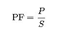
Where:
- PF = Power Factor (unitless, range: 0 to 1)
- P = Real Power (Watts, W)
- S = Apparent Power (Volt-Amperes, VA)
2. Apparent Power Formula:
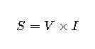
Where:
- V = RMS Voltage (Volts)
- I = RMS Current (Amperes)
3. Real Power Formula:
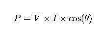
Where:
- θ = Phase angle between voltage and current
- cos(θ)=PF
4. Reactive Power (Q):
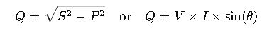
Where:
- Q = Reactive Power (VAr)
5. For Nonlinear Loads (e.g., VFDs, computers):

Where:
- Displacement PF: Due to phase angle θ
- Distortion PF: Due to harmonics (from THD)
- Distortion PF=

Note: Power factor can be leading (capacitive) or lagging (inductive), especially important in systems with compensation or advanced electronics.
Common Variable Values
| Variable | Typical Range | Depends On |
|---|---|---|
| Voltage (V) | 110V, 208V, 220V, 380V, 480V | Regional standards |
| Current (I) | 0.1A – 1000A+ | Load size |
| Real Power (P) | 10W – 1MW+ | Equipment rating |
| PF | 0.3 – 1.0 | Load type, harmonics |
| θ (theta) | 0° – 75° | Inductive/capacitive nature |
| THD | 0% – 100% | Harmonics in power system |
Real-World Application Examples
Example 1: Calculating PF of an HVAC Compressor
Problem:
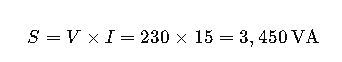
A 230V air conditioner draws 15A and has a real power consumption of 3,000W. What is the PF?
Solution:
- Apparent Power:
- Power Factor:
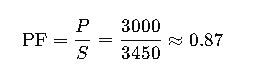
Result: The power factor is 0.87 lagging, typical for motor-driven equipment.
Example 2: Power Factor in a Data Center
Problem:
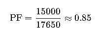
A server rack operates at 15 kW with a measured apparent power of 17.65 kVA. What is the PF and what size capacitor bank is needed to correct PF to 0.98?
Solution:
- Current PF:
- Current Reactive Power:

- Required Reactive Power at PF 0.98:
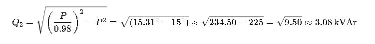
- Capacitor Bank Size:
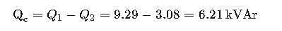
Result: A 6.2 kVAr capacitor bank is needed to correct the power factor to 0.98.
Typical Power Factor Calculator for Different Equipment (continued)
Advanced Discussion on Power Factor Correction
Power factor correction (PFC) is the process of improving the power factor of an electrical system, typically by compensating for the reactive power drawn by inductive loads (motors, transformers, etc.). Proper PFC reduces utility penalties, improves voltage regulation, and maximizes transformer/load capacity.
Methods of Power Factor Correction
| Correction Method | Application Scope | Pros | Cons |
|---|---|---|---|
| Static Capacitor Banks | Motors, HVAC, lighting systems | Cost-effective, easy installation | Fixed compensation, may over-correct |
| Automatic PFC Panels | Variable load environments | Dynamic control of PF | Higher upfront cost |
| Synchronous Condensers | Grid-level applications | Adjustable PF with inertia contribution | Expensive, mechanical losses |
| Active Power Filters | Harmonic and PF correction | Handles nonlinear loads, THD+PF solution | Complex, high cost |
| VFD Built-in Correction | Variable speed drives | Integrated correction in control logic | Only local, no network-wide impact |
Normative Context and Power Factor Penalties
International and national regulatory bodies impose standards and tariffs based on power factor. Maintaining a high PF reduces costs and ensures compliance.
Key Standards and Regulations
- IEEE 1459: Defines power components in non-sinusoidal conditions.
- IEEE 519: Regulates harmonics that indirectly affect PF.
- ANSI C84.1: Recommends power quality and acceptable PF levels.
- IEC 61000-3-2: Limits harmonic emissions in equipment, affecting PF.
- EN 50160: Defines public distribution system voltage and PF parameters in the EU.
Typical Utility Requirement: Maintain PF ≥ 0.90 (lagging) or face penalties.
Equipment Design Implications of Power Factor
Power factor influences transformer sizing, cable selection, generator capacity, and overall energy efficiency. A poor PF increases line current, which leads to:
- Increased I²R losses in cables and transformers
- Voltage drops
- Oversized electrical components
- Reduced system stability
Design Rule of Thumb:
Always size transformers and cables based on apparent power (kVA), not real power (kW).
Extended Real-World Application Example
Example 3: PF and Cable Sizing in a Manufacturing Plant
Scenario:
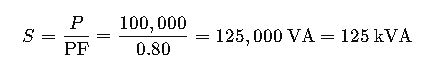
A 100 kW induction motor operates at 0.80 PF (lagging) on a 400 V system. Determine:
- Apparent power
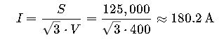
- Line current
- Required cable size
- New current if PF is improved to 0.95
Step 1: Apparent Power
Step 2: Line Current (3-phase)

Step 3: Cable Sizing
Using a maximum current of 180 A, and derating factors, select 95 mm² copper cable (per IEC 60364).
Step 4: With PF Correction (to 0.95)
Result: PF correction reduces line current by ~28 A, potentially allowing a smaller cable and improving efficiency.
How to Use a Typical Power Factor Calculator
A PF calculator for equipment typically requires the following inputs:
- Voltage (V) – Rated supply voltage
- Current (I) – RMS current from meters or specs
- Real Power (P) – From power meters, in kW
- THD (if nonlinear load) – For distortion PF
And it provides:
- Power Factor
- Apparent Power
- Reactive Power
- Suggested Capacitor Size (for correction)
Pro-Tip: Use calculators that can model both displacement and distortion PF for non-linear loads (e.g., UPS, drives).
High-Efficiency Equipment and PF Trends
Modern regulations push for higher PF values. Equipment now often integrates PFC at the design level.
| Equipment Type | PF Trend | Reason |
|---|---|---|
| Lighting (LED) | ↑ (>0.95) | Integrated PFC in drivers |
| VFDs | ↑ (>0.98) | Active rectification |
| Office Equipment | ↑ (0.90–0.99) | Power factor-corrected SMPS |
| Renewables (Solar, Wind) | → 1.0 or Leading | Grid-supportive inverter controls |
| EV Chargers (Level 2–3) | ↑ (>0.95) | Must meet IEC 61851, UL 2202 PF specs |
Frequently Asked Questions (FAQs)
What is a typical power factor for industrial motors?
A: Most industrial induction motors operate at a power factor of 0.80 to 0.92 lagging under full load. However, at no load or partial load, the power factor can drop significantly—sometimes below 0.30. Power factor correction is often needed for large motor installations.
Why is power factor important in electrical systems?
A: Power factor directly affects the efficiency, cost, and stability of electrical systems. A low power factor increases line current, causing higher losses (I²R), voltage drops, and utility penalties. Maintaining a PF close to 1.0 ensures optimal energy usage and compliance with standards like IEEE 1459 or IEC 61000.
What types of equipment typically have low power factor?
A: Equipment that includes inductive or non-linear loads tends to have low power factor, including:
- Fluorescent lighting with magnetic ballasts (PF 0.5–0.7)
- Arc welders (PF 0.3–0.6)
- Large motors at no load
- UPS systems
- Computers with low-quality power supplies
How can I improve the power factor of my system?
A: Methods include:
- Installing capacitor banks for inductive load compensation
- Using synchronous condensers for dynamic correction
- Applying active power filters for nonlinear loads
- Selecting equipment with built-in PFC circuits
- Designing with VFDs that include displacement and distortion correction
What is the difference between lagging and leading power factor?
A:
- Lagging power factor occurs when current lags voltage (typical in inductive loads like motors and transformers).
- Leading power factor occurs when current leads voltage (seen in capacitive loads or over-corrected systems).
Utilities often penalize both extremes if they deviate too far from unity.
Can a power factor be greater than 1?
A: No. Power factor ranges from 0 to 1. A PF of 1 (unity) means all power is used effectively as real power. If measurements suggest PF > 1, it’s typically due to instrument error or incorrect parameter inputs.
Does harmonic distortion affect power factor?
A: Yes. Harmonics introduce a distortion power factor (DPF) component. Even if displacement PF is good, overall true PF may be poor due to high Total Harmonic Distortion (THD). This is common in VFDs, computers, and LED lighting.
Is there a legal or regulatory requirement for power factor?
A: Yes. Most utilities require customers to maintain a PF of ≥ 0.90 lagging. Below this, penalties may apply. Additionally, standards such as:
- IEEE 519
- IEC 61000
- EN 50160
provide guidelines for acceptable power factor and harmonic content in public networks.